
1991 BMW 850i
page 11
Here's how it looks in the car...
This is the main screen after boot up which after some work now takes <20 seconds. Outside temperature is pulled from the I-bus (existing temp sensor).
If a Bloothtooth device is connects it will be indicated so.
The LCD screen is a capacitive touch... much better than the resistive touch I initially used.
This is the Vehicle info screen (MID). 'Last oil service' and battery voltage are new functions you won't find on the standard MID. Battery voltage is measured directly by an ADC and is very accurate (a less accurate version is available on the I-BUS... an extended MID function). Last Oil service is a reset-able parameter that is calculated using vehicle mileage extracted from the I-Bus and a stored value. TPMS is the latest addition. Time is displayed from a very accurate Real Time Clock (RTC), I also display the EKM's clock which should be close.


Warnings or touching any of the reset-able/configurable items pops up a dialog box (in this case a response to the CHECK button).

'E31 INFO' pops up some useful info incase I forget it (this is user editable)...

The MP3 music player has several visualization options (I'm using Kodi). This visualization was developed by Jack Tirol.

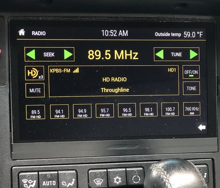
HD Radio control with decoded program info...

Bluetooth uses an inexpensive bluetooth module and supports music streaming from my iphone and hands free telephone.
Pressing 'Voice Assist' allows my Iphone to be easily controlled by voice commands. The Bluetooth module allows an emergency or one-touch number to be called which I have set to 'Call Tina'.

Radio and MP3 player info and controls are viewable on the main screen when playing.

On-board diagnostics (OBD) to monitor Fuel pressure, intake manifold vacuum and battery volts. This screen also provides access to OBD1 INPA functionality to read both DME's, EGS and EML (+2 spares for future expansion).
In case I want to access OBD1 under the hood on the standard connector, there is a switch in the side of the glovebox to disconnect the Raspbery pi. The yellow text is a note to indicate the switch position for internal diagnostics.

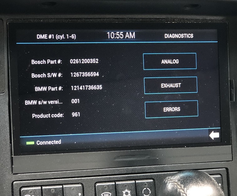
Pressing DME#1 brings up version details (read from DME).
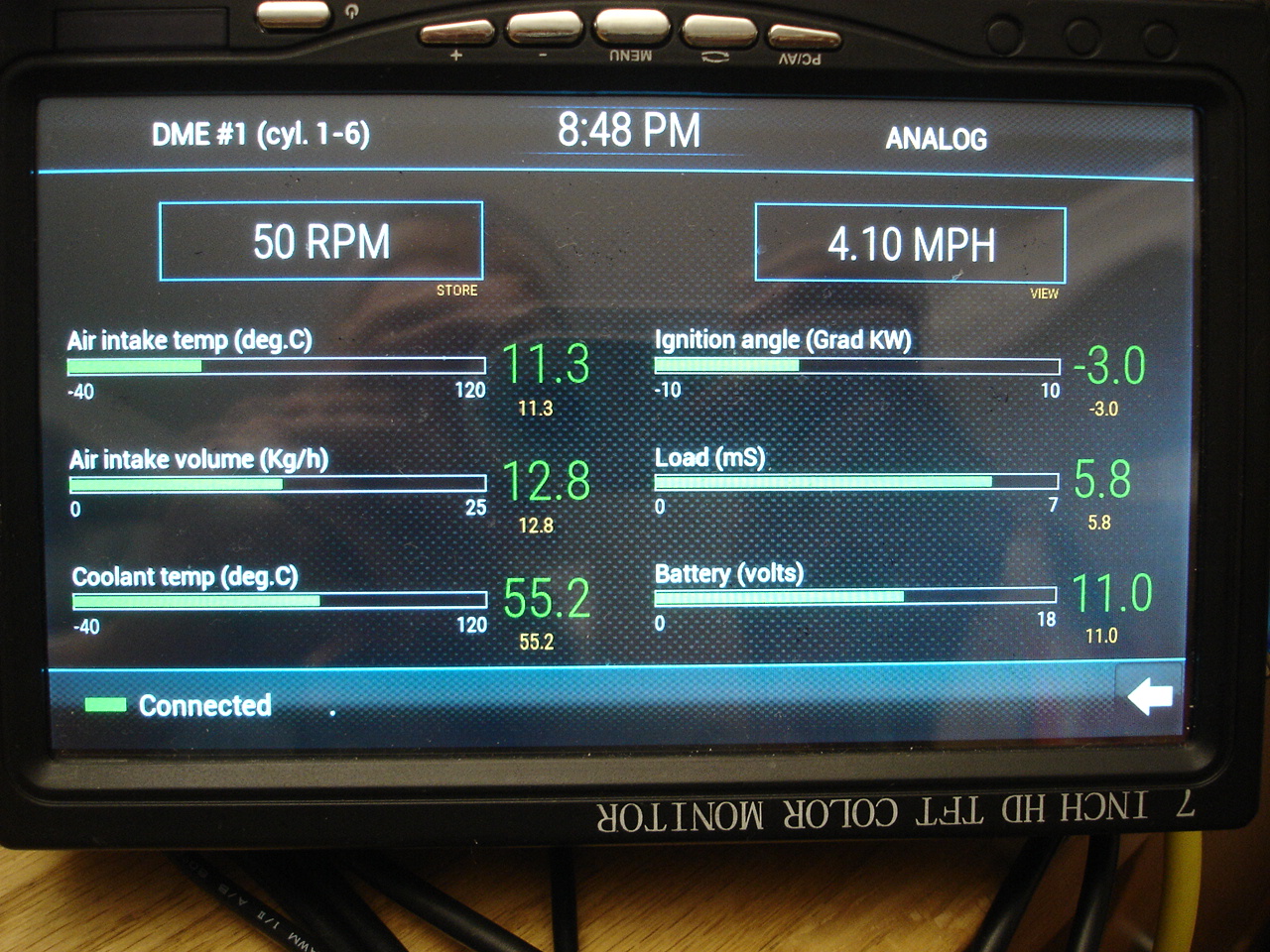
DME#1 Analog values below.

DME#1 Exhaust values below.

Read and Clear DME errors (none present in this case)

EGS diagnostics below.


Technical details...
Real time monitoring of fuel pressure, intake manifold vacuum and battery volts (very accurately I might add) is nice but I wanted to complement this with basic engine dignostics…..
This car pre-dates OBDII and instead has a multipin connecter under the hood which provides access to the car’s TxD/RxD bus (sometimes referred to as K/L-lines). BMW service tools ‘INPA’ and ‘DIS’ connect to this bus with an ADS interface. There are a few designs on the web for an ADS interface that will allow you to connect a standard RS232 PC com port (you can see details of the one I built on this site) and software can be downloaded if you search for it. But this software is designed for a Windows PC and I'm using a Raspberry pi and Linux! It should also be noted that some modules do not communicate at standard data rates which may confuse a PC UART.
I found little to no technical information on the web for the E31 TxD/RxD protocol. Most of the information presented here I reverse engineered... by connecting INPA to my car and capturing the serial messages sent back and forth. Looking for patterns in the data I was able to separate the message boundaries. At first I had hoped the protocol would be similar to I-Bus for which I was familiar but it turned out to be quite different. After a lot of searching I stumbled across some information that began to explain things and the data I captured began to make sense.... early BMW’s (Bosch Motronic) use a protocol called KW-71 for diagnostics to the DME, EML and EGS (other modules in the car use a different protocol).
Once the basic protocol was understood (see the diagram below) I built an emulator (software tool running on a PC) to mimic the messages sent by the DME (and later the EML) to INPA. Connecting INPA to this tool in place of the car allowed me to manipulate the response messages to INPA and hence learn how they are mapped to the displayed values (which bytes carry which information). Once I had this emulator working nicely with INPA I collected all the information I needed to design my own diagnostics display program coded in Python to run on the Raspberry Pi.
Below are details of the KW-71 Protocol when addressing one of the DME’s in my 850i (there are some slight differences when connecting to the EML and EGS).
All modules sit on a shared TxD/RxD bus (2 wires) and are in listen only mode until awakened. The awakening or addressing process for the DME's takes place at the blistering speed of 5bps (8N1) on the RxD line (or L-Line). A single byte '0x10' will awaken DME #1 and '0x14' will awaken DME #2 (850i has 2 x DME’s). Since further communications takes place on the single wire TxD line (at 9600bd 8N1), you can only talk to one module at a time and you each take turns to talk (see protocol diagram below).
After sending a wake up command (INPA will try 3 x times before giving up) the DME responds by sending 0x55, 0x00, 0x81 on the TxD line to which diagnostics responds with 0x7E (acknowledge). At this point the communications channel has been established and both parties can now exchange information on the TXD line (RXD is no longer used). The timing of these messages is critical which later led me to implement this interface using an Arduino (Raspberry cannot reliably maintain the required timing accuracy).
The first byte of every message indicates it’s length. It is the number of additional bytes that follow in the message or you could say it's total message length minus the first byte.
The second byte is a message counter that increments by one for every message sent. It starts at 0x00 and wraps around at 0xFF.
The third byte signifies the type of message; for example 0xF6 indicates asci text and 0x09 is a NOP (no operation) or 'keep alive' message. The latter does nothing but keep the communication channel alive (without it the DME will go back to sleep mode).
The last byte of every message is always 0x03.
The DME and Diagnostics computer (INPA) take turns to transmit 1 x message at a time and this process is maintained to keep the exchange alive. If neither have anything useful to transmit they send a NOP message.
No CRC or checksum is sent…. Instead, every byte sent (except the end of message identifier) is inverted and echoed back to the sender. This is one aspect of this protocol that makes it very inefficient and slow!

Below are the messages sent between INPA and one of my DME’s upon wakeup;
The wakeup sequence initially conveys basic information about the DME being accessed (it’s part number, revision, etc). If you look at a DME module you will see these same numbers on its labels.
Once the basic information is sent NOP (no operation) messages are exchanged to keep the link alive until the diagnostic computer requests information...
car orig 55 00 81 (I’m awake
message)
inp ack 7E
car orig 0D 01 F6 32 35 33 30 30 32 31 36 32 30 03
ascii 2530021620 reverse= 0261200353
inp ack F2 FE 09 CD CA CC CF CF CD CE C9 CD CF
inp orig 03 02 09 03
car ack FC FD F6
car orig 0D 03 F6 37 33 35 36 35 33 37 36 32 31 03
ascii 7356537621 reverse= 1267356537
inpa ack F2 FC 09 C8 CC CA C9 CA CC C8 C9 CD CE
inp orig 03 04 09 03 NOP
car ack FC FB F6
car orig 0A 05 F6 30 37 33 36 33 37 31 03
ascii 0736371 reverse= 1736370
inp ack F5 FA 09 CF C8 CC C9 CC C8 CE
inp orig 03 06 09 03
NOP
car ack FC F9 F6
car orig 06 07 F6 31 30 30 03 ascii
100 reverse = 001
inp ack F9 F8 09 CE CF CF
inp orig 03 08 09 03 NOP
car ack FC F7 F6
car orig 06 09 F6 30 37 30 03 ascii
070 reverse = 070
inp ack F9 F6 09 CF C8 CF
inp orig 03 0A 09 03 NOP
car ack FC F5 F6
car orig 03 0B 09 03 NOP
inp ack FC F4 F6
inp orig 03 0C 09 03 NOP
car ack FC F3 F6
car orig 03 0D 09 03 NOP
inp ack FC F2 F6
I wanted to read and display the analog and exhaust values along with some of the digital values and decoded error messages.
Here’s what the analog read looks like. INPA sends 2 x NOP messages between each information request. This slows down the INPA update speed so I tried removing these to speed things up but the values did not update correctly so it appears this protocol must be followed.
Retrieve Analog values
There are 7 register reads 0x 00 37, 00 38, 00 55, 00 40,
00 36, 00 3C, 00 8B that repeat when on this page in INPA (first 3 are shown
below);
Inpa req 03 D0 09 03
NOP
DME ack FC 2F F6
DME req 03 D1 09 03 NOP
Inp ack FC 2E F6
Inpa req 06 D2 01 02 00 37 03 Request 1
DME ack F9 2D FE FD FF C8
DME reply 05 D3 FE 00 00 03 Value 1
Inpa ack FA 2C 01 FF FF ()
Inpa req 03 D4 09 03 NOP
DME ack FC 2B F6
DME req 03 D5 09 03 NOP
Inpa ack FC 2A F6
Inpa req 03 D6 09 03 NOP
DME ack FC 29 F6
DME req 03 D7 09
03 NOP
Inpa ack FC 28 F6
Inpa req 06 D8 01 02 00 38 03
Request 2
DME ack F9 27 FE FD FF C7
DME sends 05 D9 FE 00 00 03 Value 2
Inpa ack FA 26 01 FF FF
Inpa sends 03 DA 09 03 NOP
DME ack FC 25 F6
DME sends 03 DB 09 03 NOP
Inpa ack FC 24 F6
Inpa sends 03 DC 09 03 NOP
DME ack FC 23 F6
DME sends 03 DD 09 03 NOP
Inpa ack FC 22 F6
Inpa req 06 DE 01 02 00 55 03 Request 3
There are 5 register reads when monitoring exhaust
values... 0x
00 9D, 02 11, 02 07, 02 01, 02 62
Inpa req 06 96 01 02 00 9D 03 Retrieve 1
DME ack F9 69 FE FD FF 62
DME sends 05 97 FE 00 00 03 Value 1
Inpa ack FA 68 01 FF FF
Inpa sends 03 98 09 03 NOP
DME ack FC 67 F6
DME sends 03 99 09 03 NOP
Inpa ack FC 66 F6
Inpa sends 03 9A 09 03 NOP
DME ack FC 65 F6
DME sends 03 9B 09 03 NOP
Inpa ack FC 64 F6
Inpa sends 04 9C 08 05 03 Retrieve 2
DME ack FB 63 F7 FA
DME sends 9D FB 00 05
03 Value 2
Inpa ack FA 62 04 FF FA
NOP
NOP
NOP
NOP
Inpa sends 06 A2 01 02 02 11 03 Retrieve 3
DME ack F9 5D FE FD FD FF
DME sends 05 A3 FE 82 02 03 Value 3
Inpa ack FA 5C 01 7D FD
NOP
NOP
NOP
There is only 1 message that conveys all digital
values;
Inpa sends 03 24 09 03
NOP
DME ack FC DB F6
DME sends 03 25 09 03
Inpa ack FC DA F6
Inpa sends 03 26 09 03 NOP
DME ack FC D9 F6
DME sends 03 27 09 03
Inpa ack FC D8 F6
Inpa req 06 28 01 0A 00 20 03 Request for
digital values
DME ack F9 D7 FE F5 FF DF
DME sends 0D 29 FE 06 DC FD 00 00 84 00 00 00 04 03 DME sends
values
Inpa ack F2 D6 01 F9 23 02 FF FF 7B FF FF FF FB
Inpa sends 03 2A 09 03 NOP
DME ack FC D5 F6
DME sends 03 2B 09 03 NOP
DME ack FC D4 F6
The error code retrieval message is below. If there are any error codes present the DME will follow the error count message with separate messages for each error present (providing the error code and conditions under which it occurred).
Sends 03 D2 09 03
NOP
Ack FC 2D F6
Sends 03 D3 09 03 NOP
Ack FC 2C F6
Inpa sends 03 D4 07 03 Inpa req
error count
DME ack FC 2B F8
DME sends 04 D5 FC 00 03 DME
returns error count
Inpa ack FB 2A 03 FF
Inpa sends 03 D6 09 03 NOP
DME ack FC 29 F6
DME sends 03 D7 09 03 NOP
Inpa ack FC 28 F6
Inpa sends 03 D8 09 03 NOP
As indicated earlier, I wrote a
Python program to emulate a DME (fool INPA into thinking it was talking to a
DME). I used this to manipulate response messages to determine what each was and
how it mapped into INPA.
This excerpt from my code explains the message protocol at least as it relates
to what is displayed in INPA. There are additional fields in many of these
messages that INPA does not appear to use (display).
# ******* DME canned address and
messages ********
# ana[1:7] address
n1=0x36
n2=0x3c
n3=0x8b
n4=0x37
n5=0x38
n6=0x55
n7=0x40
ana1=[0x05, 0xd3, 0xfe, 0xf0, 0x00, 0x03] # Battery volts = .0681 * Byte3,
Byte4 not used
ana2=[0x05, 0xd3, 0xfe, 0xff, 0x00, 0x03] # RPM = 10 * Byte3, Byte 4 not used
ana3=[0x05, 0xd3, 0xfe, 0x71, 0x00, 0x03] # Speed (Km/hr) = 1.102 * Byte3,
Byte4 not used
ana4=[0x05, 0xd3, 0xfe, 0x40, 0x00, 0x03] # air intake temp (deg.C) -33.5 +
(0.65 * Byte3), Byte4 not used
ana5=[0x05, 0xd3, 0xfe, 0xa0, 0x00, 0x03] # coolant temp (deg.C) -32.5 + (0.65
* Byte3), Byte4 not used
ana6=[0x05, 0xd3, 0xfe, 0x60, 0x00, 0x03] # ign angle = 0.75 * (96 - Byte3),
Byte4 not used
ana7=[0x05, 0xd3, 0xfe, 0x70, 0x00, 0x03] # load (mS) = .05 x Byte3, Byte4 not
used
# exhaust 1:6 address (no 2)
ex1=0x9d
ex3=0x11
ex4=0x07
ex5=0x01
ex6=0x62
#digital values address
d1=0x20
exm1=[0x05, 0xd3, 0xfe, 0x40, 0x00, 0x03] # air consumption Kg/h = 0.2 *
Byte3, Byte 4 not used
exm2=[0x05, 0xd3, 0xfb, 0x00, 0x40, 0x03] # Lambda sensor (volts) = .00484 *
Byte4
exm3=[0x05, 0xd3, 0xfe, 0xa0, 0x02, 0x03] # Not sure what Byte4 is. Lambdaint
= Byte3 - 128
exm4=[0x05, 0xd3, 0xfe, 0x85, 0x00, 0x03] # Adaption additive = Byte3 - 128,
Byte4 ??
exm5=[0x05, 0xd3, 0xfe, 0x85, 0x00, 0x03] # Adaption multiplcativ = Byte3 -
128, Byte4 ??
exm6=[0x05, 0xd3, 0xfe, 0x85, 0x00, 0x03] # Adaption TEV = Byte3 - 128, Byte4
??
digi1=[0x0d,0x29,0xfe,0x06,0xdc,0xfd,0x00,0x00,0x84,0x00,0x00,0x00,0x24,0x03]
# Digital values Byte12 xx1x xxxx (1= lambda ctr)
#
Byte11 xxx1 xxxx Status idle speed
#tc1=[0x04, 0xd5, 0xfc, 0x00, 0x03] # trouble code message Byte[3] = number of
errors
tc1=[0x08, 0xd5, 0xfc, 0x64, 0x01, 0x80, 0x80, 0x03, 0x03] # individual trouble
code message
#Byte[3]=TC#, [4]additional info, [5]x40=rpm, [6]bat volts .0681x=volts,
[7]error frequency
tc2=[0x08, 0xd5, 0xfc, 0xc9, 0x02,
0x80, 0x40, 0x03, 0x03] # [6] temp x80=48C x40=0c xa0=72c x60=24C
#
[6] load signal x60=4.8mS xa0=8mS x80=6.4mS x40=3.2mS
# Byte 4 (can be more than one)
# 00 open circuit/error not present/static error
# 01=short to B+
# 02=short to ground
# 04=not allowed
# 08=invalid working area
# 10=exhaust gas relavant fault
# 20=fault stored after re-bouncing delay
# 40=error present
# 80=sporadic error
#These are the identification messages (ascii) sent by the DME and their
meaning.
msg1=[0x0d, 0x01, 0xf6, 0x32, 0x35, 0x33, 0x30, 0x30, 0x32, 0x31, 0x36, 0x32,
0x30, 0x03] # H/W# rev
msg2=[0x0d, 0x03, 0xf6, 0x37, 0x33, 0x35, 0x36, 0x35, 0x33, 0x37, 0x36, 0x32,
0x31, 0x03] # S/W#rev
msg3=[0x0a, 0x05, 0xf6, 0x30, 0x37, 0x33, 0x36, 0x33, 0x37, 0x31, 0x03] # BMW
part# rev
msg4=[0x06, 0x07, 0xf6, 0x31, 0x30, 0x30, 0x03] # production number? reverse
msg5=[0x06, 0x09, 0xf6, 0x30, 0x37, 0x30, 0x03] # DOM reverse
msg6=[0x03, 0x09, 0x09, 0x03] # NOP
And from my Raspberry code…. the error code mapping for the DME;
tclook[0] = '#0 Undefined Fault'
tclook[1] = '#1 Fuel Pump Relay'
tclook[2] = '#2 Idle-speed controller'
tclook[3] = '#3 Injectors (2,4,6 or 8,10,12)'
tclook[8] = '#8 CHECK ENGINE light fail'
tclook[16] = '#16 Ignition system or CPS'
tclook[18] = '#18 Final Stage Pin 18'
tclook[32] = '#32 Injectors (1,3,5 or 7,9,11)'
tclook[36] = '#36 EVAP Canister Valve'
tclook[37] = '#37 Lambda Heater Relay'
tclook[41] = '#41 Air Mass Sensor (MAF)'
tclook[48] = '#48 A/C Compressor Shut Off'
tclook[54] = '#54 Voltage Supply'
tclook[63] = '#63 Torque Cnvtr Lockup Clutch'
tclook[64] = '#64 EGS/DME Connection Error'
tclook[70] = '#70 Oxygen Sensor'
tclook[73] = '#73 Road Speed Signal'
tclook[76] = '#76 Idle Speed - CO adjust'
tclook[77] = '#77 Intake Air Temp Sensor'
tclook[78] = '#78 Coolant Temp Sensor'
tclook[82] = '#82 Engine Drag Torque Control'
tclook[83] = '#83 ASC (EML)'
tclook[100] = '#100 DME Output Stage'
tclook[200] = '#200 DME Control Unit'
tclook[201] = '#201 Oxygen Control'
The messages I have chosen to implement and information I can display ….
# request info messages
ana1=[0x06, 0xea, 0x01, 0x02, 0x00,
0x36, 0x03] # Battery volts
ana2=[0x06, 0xf0, 0x01, 0x02, 0x00, 0x3C, 0x03] # RPM
ana3=[0x06, 0xf6, 0x01, 0x02, 0x00, 0x8B, 0x03] # Speed Km/h
ana4=[0x06, 0xd2, 0x01, 0x02, 0x00, 0x37, 0x03] # air intake temp
ana5=[0x06, 0xd8, 0x01, 0x02, 0x00, 0x38, 0x03] # coolant temp
ana6=[0x06, 0xde, 0x01, 0x02, 0x00, 0x55, 0x03] # ign angle
ana7=[0x06, 0xe4, 0x01, 0x02, 0x00, 0x40, 0x03] # load
exh1=[0x06, 0x96, 0x01, 0x02, 0x00,
0x9d, 0x03] # air consumption
exh2=[0x04, 0x9c, 0x08, 0x05, 0x03] # Labda sensor
exh3=[0x06, 0xa2, 0x01, 0x02, 0x02, 0x11, 0x03] # lambda int
exh4=[0x06, 0xa8, 0x01, 0x02, 0x02, 0x07, 0x03] # Adaption additiv
exh5=[0x06, 0xae, 0x01, 0x02, 0x02, 0x01, 0x03] # adaption mult
exh6=[0x06, 0xb4, 0x01, 0x02, 0x02, 0x62, 0x03] # adaption TEV
eml1=[0x04, 0x6c, 0x08, 0x03, 0x03] # EML coolant temp
eml2=[0x04, 0x72, 0x08, 0x05, 0x03] # pedal position
eml3=[0x06, 0xe6, 0x01, 0x01, 0x00, 0x2d, 0x03] # EML dig values
dig1=[0x06, 0x28, 0x01, 0x0A, 0x00, 0x20, 0x03] # idle status
clerrors=[0x03, 0xd4, 0x05, 0x03] #clear error count
rderrors=[0x03, 0xd4, 0x07, 0x03] #request error count
nop=[0x03, 0x09, 0x09, 0x03] # NOP
endcon=[0x03, 0x09, 0x06, 0x03] # end connection
Here’s some screens captured
during development….
Selected DME 1 and it is connecting...

DME 1 connected and presents its info (there is a moving string of dots on the bottom that lets you know the connection is active).

DME 1 Analog (simulated data from my emulator shown)

DME 1 exhaust

Error codes

And for the EML

EML shares the same error screen as the DME but the Analog is different

When the system was first installed in the car INPA functionality worked but would often disconnect. And when playing music at the same time it was barely usable at all. It was then I realized the KW-71 protocol is very sensitive to timing and the Raspberry is not good at this sort of thing due to its multi-tasking operating system.
So I moved the timing critical elements to an Arduino.
Below a $7 Arduino Uno connected to my TxD/RxD breadboard. A single USB cable is the only connection to the Raspberry.

This has now been migrated to an Arduino nano (Chinese clone) and a custom Printed circuit board:


The Arduino is a microcontroller and does not use an operating system.... it's timing is very predictable. The Arduino is programmed in 'C' a new language for me but was very easy to pick up, in fact I had the whole thing together and working in little over a week. And it works very solid... this really is the best combination; the low level timing sensitive protocol handled by the Arduino and the Raspberry Pi computing and presenting the collected data. I spent quite a bit of time optimizing the KW-71 protocol timing to yield the fastest but most reliable response.
To facilitate comparing the results from each DME (each side of the engine), I added a feature to store and view on screen values. You can store and save DME#1 then look at DME#2 and compare the values.
Note despite info on the web indicating otherwise... it is not possible to maintain communication with both DME's at the same time. The protocol simply does not allow this and i takes so long to access each DME that toggling between the 2 would be very slow (several seconds)
I'm not able too connect to the EML when the engine is running. My stand alone PC version of INPA does exactly the same thing so it is not a fault of my hardware. I've tried replacing my EML and both are this way. I' not sure why this is but appears it is normal.
The DMHD-1000 HD receiver RS232 control was modified to interface directly to mini-USB (connects to one of the Raspberry Pi USB ports).

The 2 pin connector under the mini-USB is for remote turn on-off. This connects directly to an I/O pin on the Raspberry and works more predictably than trying to use USB RTS (the stock method).

The tray inside the upper glove box is simply held in place by 4 x screws and once removed reveals a nice sized opening with good ventilation and cable access...
The raspberry pi, hifi sound card, HD radio and my diagnostic interface are all mounted on a sheet of aluminum that picks up 2 of inner tray mounting holes. The underside of the aluminum has a strip of foam attached where it rests on the top of the lower grove box. I later added more hardware to this plate.

Here it is wired up and very easily accessible! The black box to the left is a noise filter (later eliminated).

Below is the circuit board I made for the I-Bus interface (TH3122.4) and 2 x 4 channel ADC converters that measure Fuel pressure, Intake vacuum and battery volts. There are 3 unused inputs for future upgrades. I wrapped this in heat-shrink and its tucked behind the center console, it consumes very little power so requires no cooling.

updated 12/28/2020
I've added Bluetooth support with a very inexpensive module attached to this PWB which also includes tone controls, a real analog volume control and balanced audio outputs. The Bluetooth module supports hands free telephone and music player. I also replaced the HiFi amplifier in the car with my own design (much better sound).

Here's the updated setup...


TPMS
I added TPMS using external sensors (built into valve stem caps). These are available inexpensively on Ebay. They activate when the car is moving.

The receiver is mounted ~ mid-point under the car which is important for good reception from each wheel and reliable operation. I installed a longer USB cable (~8 ft) which snakes up behind the passenger front wheel well and through the floor pan (had to drill one small hole)

Here's a peek inside the receiver... very simple circuit with a standard TPMS receiver IC, a PIC microcontroller and a CH340 USB interface IC.

Some additional technical details below:
This is the I-Bus interface. It interfaces directly to the Raspberry UART and GPIO for CTS.

This is the interface to the diagnostics interface (later modified with the addition of an Arduino). A relay isolates the circuit from the car's diagnostic bus when not in use and ties the signals off as does the cap on the diagnostic connector under the hood (cap must be removed or modified to use this circuit).

This was the prototype prior to designing a printed circuit board.

Below is the initial circuit I came up with to modulate the LCD backlight intensity. It works but a better version is underway.

The circuit below delays power removal from the Raspberry Pi for about 15 mins after turning off the car. This avoids the start up delay (about 1 minute) when stopping for fuel or a quick grocery stop. It tells the Raspberry to shut down shortly before cutting off the power... allowing for a safe shutdown. In the off state it consumes no power.

This block diagram shows how it is all hooked up.

Here is a sample of the PC program I wrote to capture I-Bus messages (time stamped hex and decoded messages):
2017-02-12 17:40:25.640000 02:05:01:90:82:02:16 EKM to MID Average_speed= 28.2 MPH
2017-02-12 17:40:25.656000 02:07:01:c0:00:00:ff:ff:c4 EKM to MID inspection= ff:ff:00:00
2017-02-12 17:40:25.671000 02:0b:01:be:56:7a:43:82:ff:ff:ff:ff:5b EKM to MID unknown2= ff:ff:ff:ff:82:43:7a:56
2017-02-12 17:40:25.687000 02:06:ff:a4:f0:0b:82:26 EKM to ALL Mileage= 134128 miles
2017-02-12 17:40:25.703000 02:04:ff:a5:00:5c EKM to ALL unknown3= 00
2017-02-12 17:40:25.718000 02:05:ff:fc:07:12:11 EKM to ALL impulses_per_Km= 12:07
2017-02-12 17:40:25.734000 02:04:01:ac:01:aa EKM to MID codelock= 01
2017-02-12 17:40:25.750000 02:05:01:ae:00:00:a8 EKM to MID unknown1= 00:00
2017-02-12 17:40:25.765000 02:06:ff:bc:fd:5f:20:c5 EKM to ALL unitcoding= 20:5f:fd
2017-02-12 17:40:25.781000 02:05:ff:bd:01:01:45 EKM to ALL language= 01:01
2017-02-12 17:40:25.796000 02:07:01:86:00:00:00:00:82 EKM to MID timer= 00:00
2017-02-12 17:40:25.812000 02:07:01:87:00:00:00:00:83 EKM to MID freezetimer= 00:00
2017-02-12 17:40:25.828000 02:05:ff:83:38:26:65 EKM to ALL time= 06:38PM
2017-02-12 17:40:25.843000 02:07:ff:82:02:12:17:07:78 EKM to ALL Date= 02:12:17
2017-02-12 17:40:25.859000 02:04:01:9c:00:9b EKM to MID speed_limit_status= 00
2017-02-12 17:40:25.875000 02:05:01:9d:ff:ff:9b EKM to MID factory_speed_limit= ff:ff
2017-02-12 17:40:25.890000 02:05:01:98:ff:ff:9e EKM to MID default_speed_limit= ff:ff
2017-02-12 17:40:25.906000 02:05:01:99:ff:ff:9f EKM to MID speed_limit= ff:ff
2017-02-12 17:40:25.921000 02:04:01:8c:00:8b EKM to MID unknown4= 00
2017-02-12 17:40:25.937000 02:05:01:8e:ff:ff:88 EKM to MID park_vent_heater_1= ff:ff
2017-02-12 17:40:25.953000 02:05:01:8f:ff:ff:89 EKM to MID park_vent_heater_2= ff:ff
2017-02-12 17:40:25.968000 02:05:ff:a0:15:06:4b EKM to ALL outside_temp= 61.5 degF
2017-02-12 17:40:29.078000 02:05:ff:83:39:26:64 EKM to ALL time= 06:39PM
2017-02-12 17:40:32.906000 02:04:ff:fa:01:02 EKM to ALL i_am_here= 01
2017-02-12 17:40:32.968000 02:05:ff:f8:00:00:00 EKM to ALL ign_key_position= OFF
2017-02-12 17:40:33.015000 02:05:ff:fb:07:06:02 EKM to ALL heartbeat= 06:07
2017-02-12 17:40:33.062000 02:04:08:81:00:8f EKM to unk unknown
2017-02-12 17:40:36.953000 02:07:01:c0:00:00:ff:ff:c4 EKM to MID inspection= ff:ff:00:00
2017-02-12 17:40:37 02:0b:01:be:56:7a:43:82:ff:ff:ff:ff:5b EKM to MID unknown2= ff:ff:ff:ff:82:43:7a:56
2017-02-12 17:40:37.031000 02:06:ff:a4:f0:0b:82:26 EKM to ALL Mileage= 134128 miles
2017-02-12 17:40:37.078000 02:04:ff:a5:00:5c EKM to ALL unknown3= 00
2017-02-12 17:40:37.125000 02:05:ff:fc:07:12:11 EKM to ALL impulses_per_Km= 12:07
2017-02-12 17:40:37.140000 02:04:01:ac:01:aa EKM to MID codelock= 01
2017-02-12 17:40:37.156000 02:05:01:ae:00:00:a8 EKM to MID unknown1= 00:00
2017-02-12 17:40:37.171000 02:06:ff:bc:fd:5f:20:c5 EKM to ALL unitcoding= 20:5f:fd
2017-02-12 17:40:37.187000 02:05:ff:bd:01:01:45 EKM to ALL language= 01:01
2017-02-12 17:40:37.203000 02:07:01:86:00:00:00:00:82 EKM to MID timer= 00:00
2017-02-12 17:40:37.218000 02:07:01:87:00:00:00:00:83 EKM to MID freezetimer= 00:00
2017-02-12 17:40:37.234000 02:05:ff:83:39:26:64 EKM to ALL time= 06:39PM
2017-02-12 17:40:37.250000 02:07:ff:82:02:12:17:07:78 EKM to ALL Date= 02:12:17
2017-02-12 17:40:37.265000 02:04:01:9c:00:9b EKM to MID speed_limit_status= 00
2017-02-12 17:40:37.281000 02:05:01:9d:ff:ff:9b EKM to MID factory_speed_limit= ff:ff
2017-02-12 17:40:37.296000 02:05:01:98:ff:ff:9e EKM to MID default_speed_limit= ff:ff
2017-02-12 17:40:37.312000 02:05:01:99:ff:ff:9f EKM to MID speed_limit= ff:ff
2017-02-12 17:40:37.328000 02:04:01:8c:00:8b EKM to MID unknown4= 00
2017-02-12 17:40:37.343000 02:05:01:8e:ff:ff:88 EKM to MID park_vent_heater_1= ff:ff
2017-02-12 17:40:37.359000 02:05:01:8f:ff:ff:89 EKM to MID park_vent_heater_2= ff:ff
2017-02-12 17:40:37.375000 02:05:ff:a0:15:06:4b EKM to ALL outside_temp= 61.5 degF
2017-02-12 17:40:37.390000 02:05:01:92:40:81:55 EKM to MID MPG_1= 14.0
2017-02-12 17:40:37.406000 02:05:01:93:ff:7f:15 EKM to MID Reset;_MPG_2= --.-
2017-02-12 17:40:37.421000 02:05:01:a2:ff:ff:a4 EKM to MID distance= ff:ff
2017-02-12 17:40:37.437000 02:07:01:88:ff:ff:ff:ff:8c EKM to MID time_of_arrival= ff:ff
2017-02-12 17:40:37.453000 02:05:01:96:34:02:a6 EKM to MID Range= 234 miles
2017-02-12 17:40:37.468000 02:05:01:90:82:02:16 EKM to MID Average_speed= 28.2 MPH
2017-02-12 17:40:37.484000 02:05:ff:a0:15:06:4b EKM to ALL outside_temp= 61.5 degF
2017-02-12 17:40:41.734000 09:04:02:81:02:8c ZKE to EKM passenger door open
2017-02-12 17:40:41.781000 02:03:09:01:09 EKM to ZKE message_acknowledge= 09
I decoded everything of use to me but there are still a few messages i've not been able to figure out.