
1991 BMW 850i
page 10
The BMW HomeLink Garage door opener is a nice addition to the 850i and was installed in the panel above the rear view mirror.
I used a dremel to cut out the opening and then cleaned it up with a utility knife blade (as a scraper).
The HomeLink unit was purchased on Ebay for $14 shipped! BMW part number is 6-9I9-879.
There is very little clearance behind this panel so it is necessary to butcher the HomeLink a little.
A piece of foam (not shown) was glued to the back of the circuit board to hold it in-place and prevent shorting any traces to the sunroof motor.


Car PC Project


The following details my car computer added in place of the existing Radio and OBC. It is built around a Raspberry Pi running Kodi with custom addons. Each addon is written in python (a programming language I had never used before this project). Kodi is an open source multimedia platform running under the Linux OS in this project and makes UI development relatively easy once you become familiar, and of course it makes audio and video playback easy.
This project was started in Dec 2016 and has morphed several times since as I make improvements and add new capabilities. It is now quite refined and works very well.
The most recent iteration adds TPMS, Bluetooth (hands free calling and music streaming) also built-in diagnostics now includes the transmission (EGS). I have changed out the audio amplifier... I'm no longer using the stock BMW amp in the trunk as I could not get rid of alternator whine. I’m now using an amplifier with 6 x TPA3116’s (a separate amplifier for each side door, footwell and rear deck). The volume control is a real knob which I find much more convenient than the touch screen I started out with (all other functions remain touchscreen).
Functionality now included is:
1. HD AM/FM Radio with onscreen program info.
2. MP3 player (music files stored to memory card).
3. Bluetooth hands free telephone and music streaming from my iphone.
4. MID functions (MPG, Range, avg speed, outside temperature) + some I added (Distance since last oil change, Battery volts). Pop-up windows (dialogue boxes) indicate error messages such as ‘low coolant’, ‘fasten seatbelt’, etc that would normally appear on the MID.
5. TPMS using tire pressure sensors built into valve stem caps.
6. OBD1 diagnostics (equivalent to inpa/DIS) with support for DME1, DME2, EML and EGS. I may add more later.
7. Display of fuel pressure (at each fuel rail) and intake manifold vacuum using pressure sensors (useful for diagnosing engine issues).
8. 6 x ch audio amplifier with tone control and remote volume control patched into existing wiring (connectors under center console) in such a way that all speakers are individually wired (no common ground) and with no cabling modifications to the car. I’m using stock speaker boxes with new replacement speakers.
I'm not a software programmer so learning Python consumed a great deal of my time but I have now come to appreciate this as a very versatile programming language that I now use quite often.
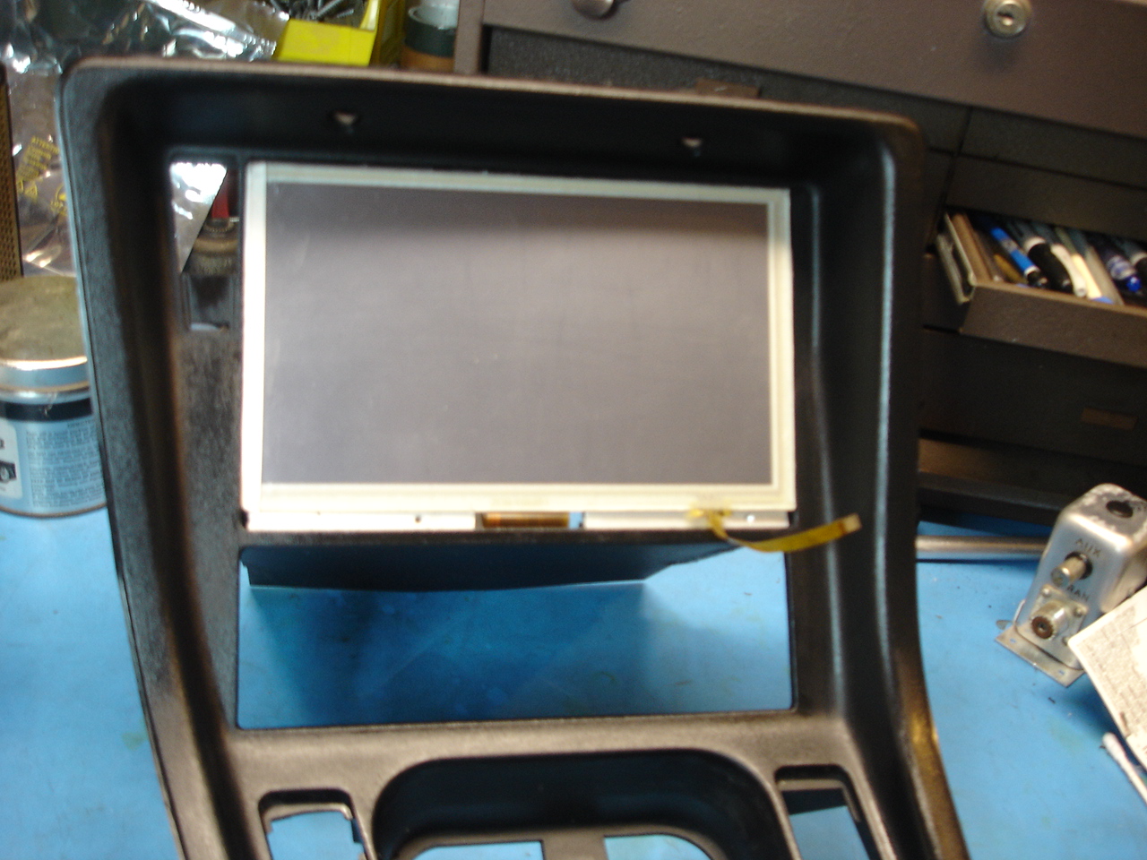
Basic fabrication
I'm using an 8" 1024x600 LCD panel (model# ZJ080NA 08A) in place of the radio and MID. It is fitted with a capacitive touch-panel (much better than the resistive panel I started out with). This panel is a little wider than the standard DIN opening so the console required some surgery....
I removed the right hand inner wall and relocated it to the right and then rebuilt the structure.

I tried a few different types of glue for re-assembly but none were strong enough fso I ended up welding it... I used superglue to tack the structure in place and then using the piece of plastic I removed from the radio/OBC divide as my welding material and an old soldering iron to melt it, I welded the pieces back together... it worked surprisingly well and is very strong! Just be sure to do this in a well ventilated area as it stinks!
It's not quite as clean looking as the original but it is very strong.

I used the same technique to repair a broken mounting post for the HVAC panel (a common issue with these cars)...
I didn't have the broken piece so I formed a piece of straight plastic around a snug fitting drill bit using a heat-gun and then welded the joint with my soldering iron.


Here is the LCD/touch panel roughed in place. I used a piece of 1/4" aluminum bar stock to fill the gap below the LCD panel with slots filed into it to clear the LCD and touch panel flex cables that wrap around to the back of the panel.
Here is what it looks like finished. The perimeter of the LCD panel is wrapped in an adhesive backed matt black vinyl sheet. The small hole you see in the accessory plate to the left of the LCD is an LED light sensor used to adjust the intensity of the LCD backlight based on ambient light (it automatically dims at night). I later added an on-off switch to this panel and did away with the auto-sensing backlight. Also replaced the on-screen volume control with a real knob!

Here's a look behind the panel...
You can see the LCD touch panel controller attached to the rear of the LCD panel with double sided tape. The HDMI LCD controller is the main PWB with a small modification to correctly drive the backlight for this LCD panel. There's also some power line filtering and a sequencer circuit on the right to control the shut down process.
The LCD panel is held in place with 4 small magnets (one at each corner) which makes it possible to remove the LCD panel to gain access behind it.
The connector at bottom mates with the original radio connector. I'm only pulling power from this connector, I patch into the speakers elsewhere.

The Raspberry Pi, HD radio module and other parts of the system are mounted in the top glovebox.
All 4 x USB ports are used (HD radio control, touch panel, OBD1 interface and TPMS). I-BUS interfaces to the Pi's serial port.

The upper glove box internal compartment was removed (just a few screws) and you can see how I mounted everything below... its easy to get to and remove if needed making code updates and/or modifications easy.

The TPMS Receiver is mounted underneath the car.

This little board interfaces the Pi to the I-Bus (MID) and pressure sensors. I covered it with heatshrink and it just floats in the wiring behind the console.
There are 3 x custom circuit boards... the one below, the tone control/bluetooth board and the OBD1 interface.

The computer displays fuel pressure using these pressure transducers which are rated 0-100psi (~ $15 ea on Ebay from China and surprisingly nice quality). They require a +5V supply and output an analog voltage proportional to pressure. I've had to replace them once so far... seems like they only last a few years. It gets pretty hot under the hood and this may be why.

It is important to use a liquid thread sealant on these fittings. Teflon tape is not recommended for fuel lines.

Here you can see the sensors fitted to the car... tucked away behind the heater control valve.
Routing cables to the pressure sensors was easy, passing through a hole to the side of the brake booster that I believe is for a clutch actuator. There is also a connection to the battery post in front of the heater control solenoids that I used to measure and display battery voltage (very accurately).

I added a similar set of sensors to monitor intake vacuum (or pressure if you have SC or TC). These sensors are rated for -14.5 psi to +30psi (typical intake vacuum is about -10psi). A lot of info can be gleaned by monitoring the intake vacuum (old school).


You can see how I routed the wiring for the intake sensors... it passes through the firewall next to the brake booster.

LCD controller
The 8" LCD/touch panel and driver came from China and were a bargain at $55 incl shipping (Ebay) but they were not without issues.... the panel was a little dim so I did some probing and found that this driver board (a generic board included with many LCD kits from China) can only source about 100mA of backlight current and my LCD panel requires a nominal 350mA for best brightness! The LCD panel also requires a few analog voltages which are derived from the same inverter that is driving the backlights and these were not set correctly either causing the intensity and contrast controls to be offset! I made some modifications to the board to correct these issues.
In this picture I'm temporarily driving the backlights directly from +12V (with a suitable current limiting resistor... 10 ohms, 2W). But it was replaced with an ambient light level controlled inverter. The video interface to the LCD is standard HDMI and an analog input is available for the reverse backup camera (yet to be installed).
