
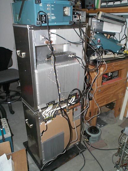
Class E AM transmitter
This project is based largely on the designs of Steve Cloutier WA1QIX. Steve's web site has everything you need to know about Class E transmitters http://www.classeradio.com/
This transmitter took me over 1 year to build. It is a completely self contained PDM modulated AM transmitter for 160, 80 and 40 meters.
The transmitter is built into 2 medium sized 19" rack cabinets that originally housed polygraph lie detectors! The lower cabinet houses the power supplies and PDM modulator. The upper cabinet houses the VFO, exciter and Power Amplifier. The scope (on top) monitors performance and the 240V variac on the ground allows for output power adjustment.
Since taking these pictures I added forward and reverse power meters to the blank panel in the center of the upper cabinet.


EXCITER
The exciter covers 160, 80 and 40m and uses a Class 'E' output stage. It is VFO controlled.
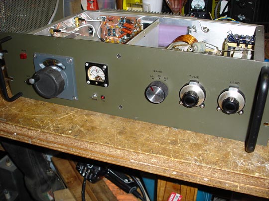
The VFO was a flea market find - a new old stock VFO and dial assembly for an FT101Z that tunes 5 - 5.5MHz (for $5!). It provides 1KHz readout on a nice lighted dial. The VFO output is mixed with one of 3 crystals to generate an output on 160, 80 or 40 meters. The small box to the left of the VFO houses a Mini-circuits mixer, selectable crystal oscillator (7, 9 or 12.5MHz) and buffer. Also there is a bank of relay switched band pass filters (one for each band) and a couple of buffer stages. The output from this section is +10dBm and all unwanted mixer spurs are better than -65dBc. This feeds the output assembly which uses 2 FQA11N40 FET's mounted on the back heatsink. The exciter provides up to 150W output on all bands.

The right section of the exciter houses the switch able tank coil assy and power supply (the exciter PA stage is powered by the main PSU assy and is adjustable to control output power). The one band switch selects the tank coil, fixed loading capacitor and heterodyne crystal/filter bank. The exciter output is matched to 50 ohms.


I had originally tried a discrete totem pole driver circuit for the exciter output but found this ran out of gas on 40m. I ended up using Maxim MAX4420 driver chips which I found to work extremely well. Other brands of this popular chip do not work nearly as well as the Maxim part. The picture below shows a close up of the exciter output. Three Maxim 4420's drive each output FET. The large relay selects additional shunt capacitance for 80 and 160m. The 4420's are driven with a simple TTL logic circuit.
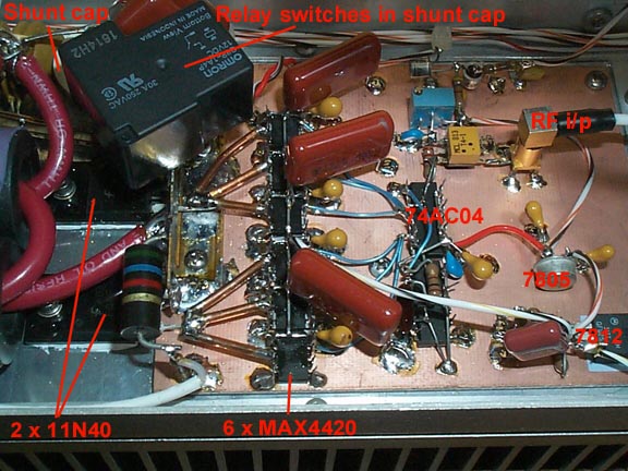
Efficiency runs about 90% on all 3 bands.
I have run this circuit up to 200W RF o/p with no problems at all on all 3 bands - more than enough to drive the 20 x 11N90 PA.
Here's a picture of the rear of the exciter:

BNC connectors are RF output (50 ohms) and Scope to allow drain waveform to be monitored.
Power Supply + PDM Modulator
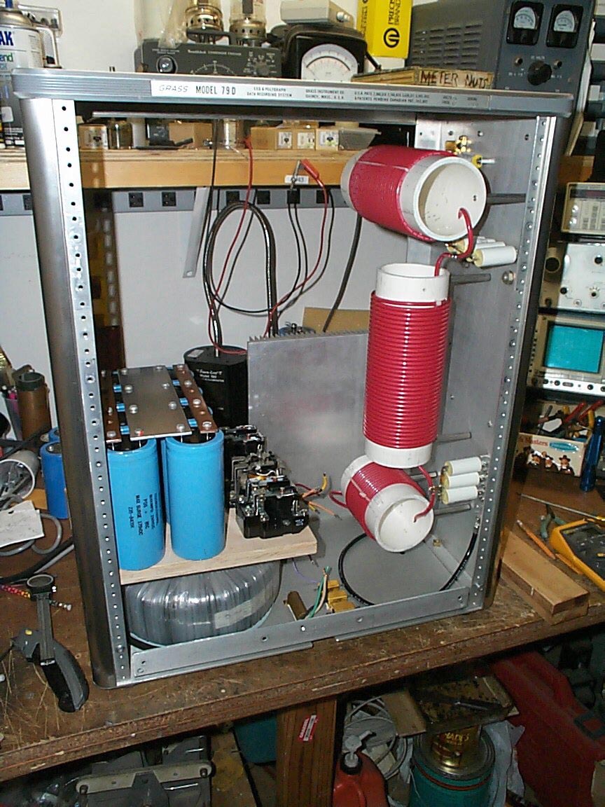
Here is the PDM filter mounted to the side wall of the lower cabinet.:

This is a 6 pole Butterworth wound on 3 1/2" PVC pipe with #8 awg wire. The capacitors are polypropylene - specifically designed for switching power supplies (metal tabs as opposed to leads) bolted directly to the aluminum wall.
The main power transformer is a large 2KVA toroid mounted to the base of the cabinet:

The smoothing capacitor bank is mounted on a shelve above the power transformer together with soft start relays.
Separate current meters monitor the drain current of each of the 4 PA sections and a switch selectable multi-meter (on right) is used to monitor other voltages in the modulator:

Here is the PDM output circuit . It uses 6 FET's and 6 Diodes. 110VDC input is on the right terminal block and the output to the PDM filter is on the left terminal block. The ground bus is screwed to the heatsink in 7 places. The input and output busses are made from surplus gold plated copper.
The FET driver circuit was built up on perf-board and is fed by an opto-isolator (driven by PDM generator).

Here is the finished modulator bolted in place. You can see the nice short connection to the PDM filter and main power supply.

The heatsink is about 10" square and doesn't even get warm.

The 3 Relays visible above are from left to right:
1. PS output relay ( 2 x 30 amp contacts in parallel)
2. Soft start relay (2 x 25A contacts in parallel)
3. HV (230V) line relay (2 x 30A)
The PDM generator was built up on a piece of copper clad. The PWM chip is lower left. Upper middle is a TL074 LPF and negative peak limiter. -12V, +12V and +5V regulators to the right.
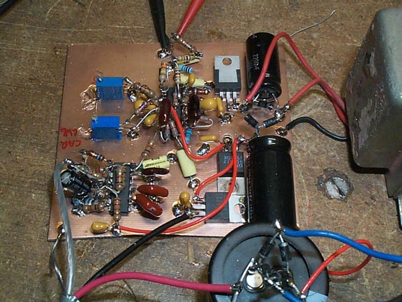
The PDM generator is mounted on a shelve above the main capacitor bank. A power sequencing and over current protection circuit is visible behind the PDM generator (also built on perf board).
The sequencing circuit is a simple circuit using relays and a RC delay. A combination of OR and AND connections ensures the ant relay and driver circuits are powered before and after the PA is turned on. It works flawlessly.

Following picture is a view of the rear of the Power supply/PDM modulator. The driver (exciter output) supply is visible upper right. A T-R relay is mounted to the connector panel (top).
This picture was taken shortly before the meter switch was wired up (visible in center).


Here is the finished Power Supply and Modulator. Audio input on the left. Driver (exciter) voltage adjust in the center. Other controls are main power, over current trip reset, and PDM duty cycle adjust.

Power Amplifier
The power amplifier uses 20 x 11N90 FETS (4 x 5 FET modules). Driven in push pull the output exhibits excellent 2nd harmonic rejection:
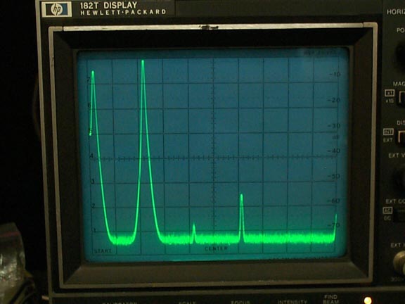
This spectrum anayzer shot above shows the output on 80m. DC marker on the left, main output to the right. 2nd harmonic is -65dBc and 3rd harmonic about -55dBc.
The PA is built on a very large heat-sink assy that spans the rear of the 19" cabinet (this transmitter requires no fans). Input and output transformers are clearly visible. The input matching circuits (50 ohm) are in the box at top - one switch selects operating band and the other is used to select the drain voltage monitor (feeds oscilloscope and allows drain voltage of each section to be monitored). This picture was taken before the shunt capacitor relays were installed.

Here's a shot of the matching networks:
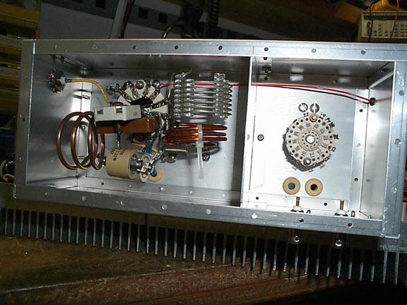
Here is the finihsed PA mounted to the rear of the cabinet with the tank coil network wired in front. A vacum cap is used for Tune and a conventional air spaced cap for Load. There are 3 band switches on this transmitter that must all be set to the desired band (exciter, PA driver circuits, PA tank).

The finished PA is RF tight. Picture below shows the lid with ventilation.

Performance is excellent at around 90% efficiency.