


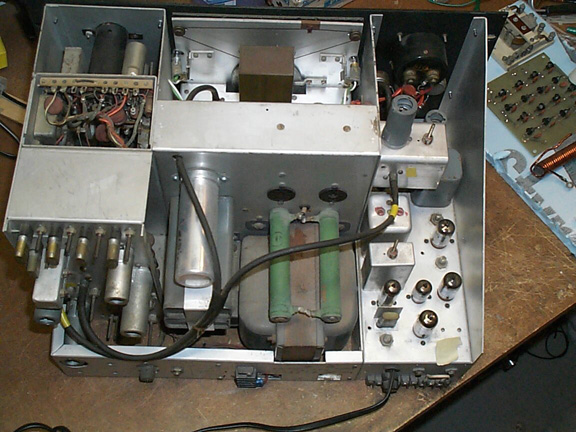

The Power Supply was rebuilt first. The chassis was completely stripped and cleaned. The transformers were dismantled and painted. I installed captive threaded studs in the chassis where the power supply screws to adjacent modules (self tapping screws were used originally and were worn loose). All the screws were replaced with stainless hardware (originals were all rusty!). After thoroughly cleaning all the pieces (Go-Jo hand cleaner), it was reassembled:


The transformer wires are all very stiff and brittle. Warming them with a heat gun allowed them to be formed into place. One or two were spliced. Everything was re-laced.
Here's the scope assembly after restoration.
One of the bathtubs was completely open (input coupling circuit). Fortunately I
had a spare in my junk box. I also replaced a few out of spec resistors and
painted the magnetic shield for the CRT and the square oil cap. Here it is
almost ready for re-assembly in the unit.

Metalwork
As I mentioned earlier, the separate modules that make up this transmitter were all screwed together with self tapping screws (original). Self tappers in aluminum work great once, but if disassembled and reassembled a few times, they quickly strip out. I am replacing them all with machine screws (stainless) and nuts or captive (pem) stud fasteners.
When I dismantled the unit I noted that the
front panel was bowed in but after removing it, it seems to be straight
(suggesting that the other metal parts were deforming it. Because of the above,
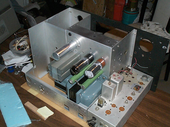
I decided to dry fit all the metal work with the new fasteners. Here you can see
the unit is pretty much stripped down and most of the metal work is in place.
The front panel appears to be holding straight (I did touch up a few bends in
the metal work). Overall, it is quite flimsy - not really strong enough to
support that large transformer mounted on its side. Originally, there was no
bottom plate on the transmitter - I will be adding one to help stiffen it
up, improve shielding and also to facilitate mounting in the cabinet (it
needs to be lifted off the cabinet bottom slightly to center up the front panel
in the cabinet opening.
So far, my impressions of this transmitter are
not so great. It is certainly a long ways from Collins quality! Just a notch or
two above homebrew. However, once I'm done, I think it will be very nice.
Purists might not like what I'm doing but I like to think Mr. Edico would
appreciate it!
Electrically, it looks sound. My only concern is the proximity of the power
transformers to all the low level circuits. Hopefully hum will not be a problem.
3-24-03
All the metalwork is finished - I cleaned and installed captive fasteners. The bottom plate is finished (drilled and holes countersunk). Everything was dry fit and the finished assembly is now very strong and rigid. I installed rubber feet on the case (can you believe the case had no feet).
The front panel meter was dismantled and cleaned. 2 of the mounting screws had broken in the past and were rather poorly glued back in place. This prevented the meter from being mounted flush with the panel. I broke off the repaired screws, cleaned up with a dremel tool and reset them using epoxy. Finished result looks great and is very strong. Once mounted in the panel you will never know.
RF Deck
At long last the RF deck is finished! This is took a lot more work than I had planned! I completely rebuilt the tank circuit. The wiring harness was removed and washed. All the tank circuit components were individually washed and the lower frequency tank coil was replaced (it was damaged). All of the switches were carefully cleaned. The ones in the exciter section were particularly dirty and oxidized. I cleaned them with Brasso using small pieces of chamois glued to the ends of tooth picks. Once the oxidation was removed, I used Deoxit and the finished results turns more smoothly and has much lower contact resistance. Several resistors and capacitors were replaced. The PA tube socket was replaced with a NOS higher quality part. Everything was thoroughly cleaned!
Here it is all back together.


I'm still waiting to hear from somebody else that has one of these! I did locate an early copy of Electric Radio which has an article about this transmitter in it. Audio quality is said to be very good!
4-30-03
This project is dragging on and on. I had no idea it was going to turn into this much work! However, it is starting to look nice and I'm hoping that it will be a solid performer when it is finished....
The front panel has been filled and touched up.
PTO has been rebuilt. The main inductor was open circuit - I found out after I rebuilt it! It is now repaired and working.
I made a new tuning dial scale. The original was faded and had several marks on it. I scanned it into my PC and then re-mastered it (let me know if you want a copy of the file?). The PTO end points adjusted easily but the tuning is not accurate mid-scale. I have no idea why - it may have always been like this? It will be easy for me to re-make the scale for accurate frequency indication but since it is all back together now I'm going to leave it for now. It's close enough and since the transmitter will always be zero beated to a receiver, absolute accuracy is not necessary.
The man/vox/stby switch shaft was too short - since new! The knob rubbed on the front panel because it had to pushed down that far for the grub screw to secure it to the switch shaft! Like I said - definitely not Collins quality. I replaced it with a new switch. The main relay contacts were quite dirty and not making good contact. These were cleaned.
It is now all back together except for the exciter chassis - it looks real nice!
Here is the exciter:
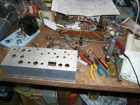
As you can see - it is completely stripped.
Here are the guts!:
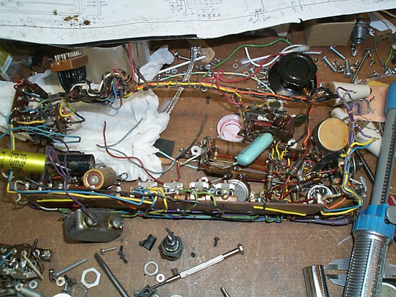
I saved the wiring harness and most of the tube sockets. They are now back in the chassis. Most of the resistors in the exciter were way off value so they and all the capacitors are being replaced.
I already have most of it back together but I did not take pictures.
I'm going to replace the audio phase shift network with a Polyphase network. It has much better performance and should yield better than 50dB of unwanted sideband rejection. The original network is quite simple and yields only minimal performance.
My schematic does not show any of the connectors that link the wiring harness together with the different modules! This all had to be figured out and seems to make sense. This is when it is good to refer back to pictures that were taken before the unit was dismantled!
I'M STILL WAITING TO HEAR FROM SOMEONE ELSE THAT HAS ONE OF THESE!! Please contact me if you do. I would be good to compare notes. I'm sure I'll have lots of performance questions once I power it up and start testing/alignment.
5-31-03
I rebuilt the mic amp/ AF lineup and VOX
circuits. These were all wired as original using the original wiring harness.
The original exciter uses a very simple phasing network that I doubt yields
particularly good unwanted sideband suppression. I elected to change it to a
Polyphase network. This uses more components (just R's and C's) but is capable
of exceptional performance! In this network the absolute accuracy of the
components is less important (I simulated in P-Spice to confirm this) than their
relative match in groups of four. Using my capacitance meter and a high
resolution ohmmeter, I was able to match the components to well below 0.1%. The
network is designed for 200Hz to 3.5KHz operation and a theoretical unwanted
sideband rejection of ~ 60dB. I am achieving a very easy 50+ dB and it does not
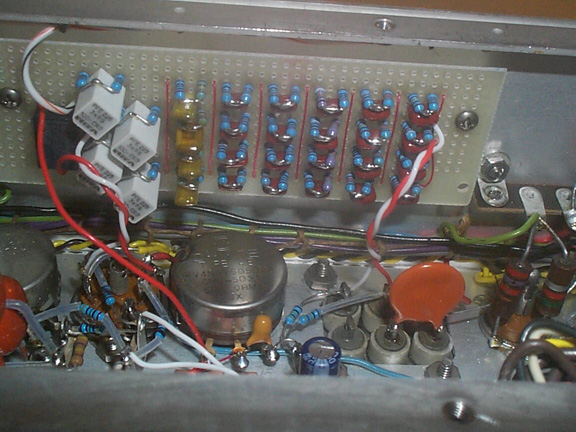
change when I shift sidebands! You can see the phase shift network built up on a
perf board below. It connects into the existing audio stages with little
modification and is mounted in the same place as the original network.
The original exciter design is noted for
drifting (with temperature) and compromise when adjusting for unwanted sideband
rejection in each sideband. A previous owner of this transmitter had moved 3 of
the phasing adjustments to the front panel because of this. I wanted it to look
close to original and so filled in the front panel holes. I'd also like this rig
to put out a nice signal. Because of this I upgraded the phase shift network as
described above. I used metal film resistors as opposed to carbon for improved
thermal stability.
I also modernized the balance modulators. I'm using a pair of Mini-Circuits
SRA-1 mixers and a Mini-Circuits PSC2-1 combiner. With no adjustment at all I am
getting >50dB of carrier suppression! Lashed up on the bench I was getting
>50dB of unwanted sideband suppression in each sideband. The original
balanced modulators used solid state diodes so this change falls well within my
range of acceptability!
The SRA-1 mixers have a 50 Ohm port impedance and the cathode follower in the
Audio section of the original circuit is not able to drive such a low impedance.
I had to add an emitter follower in each audio leg (2N3904 transistor!) to drive
the mixers. It works great. I built a small rectifier
and voltage doubler to generate 12VDC from the filament voltage to power the
2N3904's. In an effort to reduce the potential for hum pickup I also used very
small relays to switch the phasing network output (for USB/LSB) and also to
configure it for AM. I also redesigned the 90 deg phase shift network for the
carrier oscillator. I'm using a quadrature hybrid circuit (bifilar inductor and
2 capacitors). It seems to work well and is mounted in the same coil can that
housed the original.
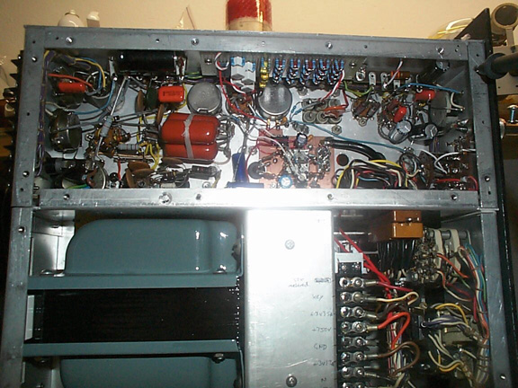
Here you can see the finished exciter section. The SRA-1 mixers are mounted on the piece of copper clad in the center.
Below is the finished transmitter all back together.
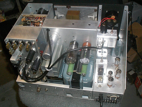
I paired it up with my 75A4 for initial on air tests. It works great!

I have been using this rig to check into the Collins net for the past few weeks now and It does a good job. Always gets excellent audio reports (even on AM!).