32V2 Restoration
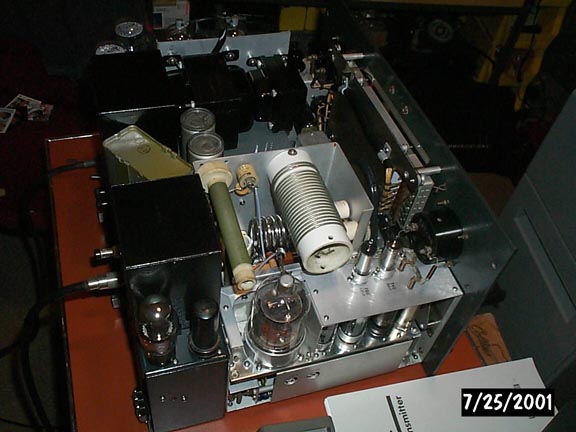
Here are some pictures of a 32V2 restoration I completed a few years ago. Unfortunately I did not keep any 'before' pictures but I can assure you it looked nothing like this. I repainted all of the iron and the power supply chassis.
Read on and you'll find another 32V2 that I restored.

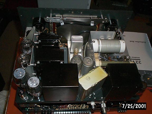

This is a 2nd 32V2 I restored:
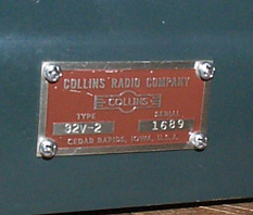
This is S/N 1689 - a late one I think?
The LV transformer had erupted in this one! Black tar was everywhere. It had seeped into the wiring harness, RF deck, and all over the power supply. The previous owner had designated this a part unit. I'm guessing that heat somehow caused the potting compound to turn into tar. Unlike potting compound which dries hard, this tar was soft and sticky!
One of the reasons for stripping this one down first was to clean up all this tar. But I would have stripped it anyways because that is the way I always do things!
Here is the modulator after restoration. It was completely stripped, cleaned and rebuilt. The oil caps are new ones!

The RF deck was also completely stripped, cleaned and rebuilt. All of the 0.01uF decoupling caps that are buried in the bottom have been removed and will be replaced with modern ceramic disks. The original caps often fail and are so difficult to get at that it makes good sense to replace them all while things are apart.
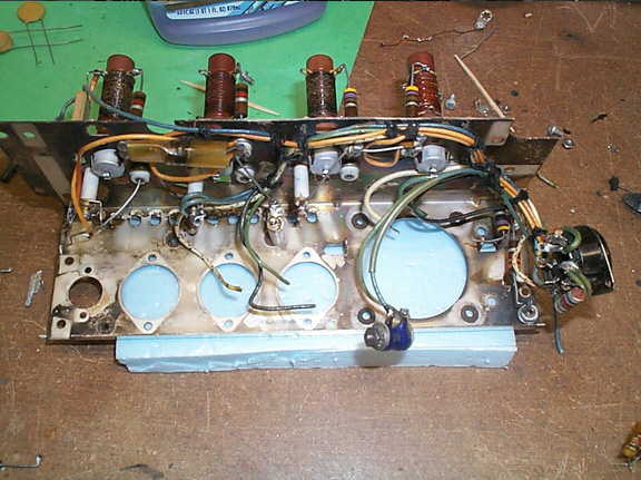
All the metal was cleaned (not polished).
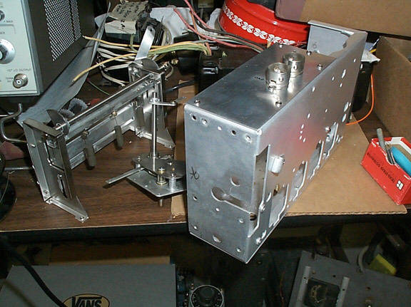
The tube sockets are the originals, reinstalled after being thoroughly cleaned.

The 100pF ceramic coupling caps are the original parts with the heat-shrink covering replaced! Most of the resistors have been replaced.


The mica caps in the switch assembly all checked good and since they are relatively easy to get at (and replace if necessary), I have not replaced any them. The switch wafers have been carefully cleaned with deoxit (applied only to the metal parts). All of the wiring is as close as possible to original. The screen decoupling cap (mica) has also been changed for a modern ceramic equivalent (it is a very common failure item).

As usual, all of the hardware has been replaced with new stainless.
Here is the PSU Deck after being stripped down and cleaned:
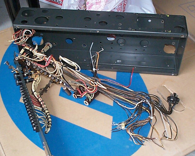
The wiring harness was unlaced to clean off the tar which had seeped into it (notice the discolored wire).
I obtained a salvaged 32V2 LV transformer from another transmitter but was a very disappointed to find that it had an internal short! After some hesitation I decided to bite the bullet and order a replacement transformer from Peter Dahl. At $155 it was not cheap but I have to say that it is a very well made unit and it is an Exact Replacement!
First job was to remove the old transformer from the case. I used a heat gun to heat the outside sufficiently to melt the potting material in contact with the case. I was then able to slide the case off revealing the transformer embedded in potting material. Rather than melt the material and have it run off, I found that if I heated it with my heat gun, it would soften up and I could break it off in chunks. I removed most of it and then removed the old transformer. The remains of the potting material were then removed with a rag and mineral spirits. The base contacts were cleaned up in preparation for the new transformer.
Here is the base and frame after cleanup with the Dahl transformer ready to wire in. Notice that the Dahl transformer is an exact fit (this really is an exact replacement). All the wires are Teflon and all are marked with the corresponding pin number on the base making wiring it in a breeze.
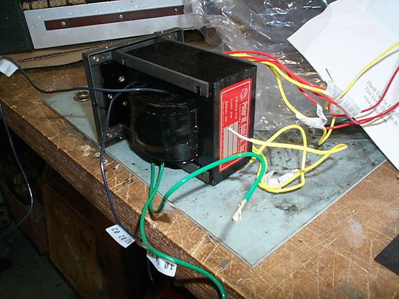
Here it is wired in and bolted in place. I'm not sure if it makes an difference, but I ran a length of heatshrink down each of the bolts (many originals used a cardboard tube). My theory is it helps prevent the bolt from acting as a shorted turn (through the frame) - there is also an insulating washer below the head of each screw.
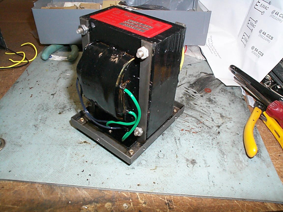
All that is left is to slide on the cover and screw it in place. There were some small air gaps around the base and cover once secured so I ran a strip of Kapton (high temp) tape along the joint to prevent potting material seeping out during the potting process.
I had saved the original potting material. The next part is rather smelly so do it outdoors! I went to the local dollar store and bought a cheap cooking pan for $1. I have an outdoor gas burner that I used to slowly melt the original potting material in the pan. Stir it when it is all melted to make sure it is a consistent thickness.
The transformer needs to be pre-heated to about 150 deg.F I did this in the kitchen oven. Need to leave it in there for an hour or so at least.
Then bring the transformer outside and pour the potting material in (down each side of the case).
Here's the finished product - about as close to original as you could ever hope to get!

All that's left is to install the lid and give it a new coat of paint.
Here's the rest of the iron (already painted) and misc other parts cleaned and ready for the rebuild.

And now it all goes back together:

The new LV transformer, Relay and low voltage rectifier are wired back in. Relay has been cleaned (including contacts). New heat shrink on the relay wring. The LV rectifier wiring is new (notice it is not stained dark as was the original).

Here you can see my harness lacing technique. I hold things in place with tie wraps first. After the lacing is done I cut away the tie wraps.
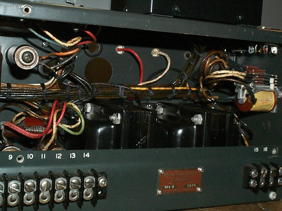

The power supply deck is all back together now (except for the power cord).
Not documented is the PTO which was also rebuilt, baked, resealed and recalibrated.
12-27-03; It is all back together now. Here are some pictures:
My camera is starting to show its age - it actually looks a lot better than the pictures!
Nothing is polished, it is just very clean. I wanted the closest I could get to 'original new in box' looks. I think it is pretty close.


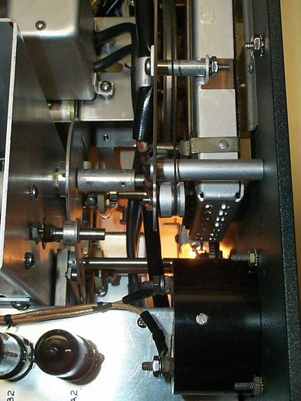
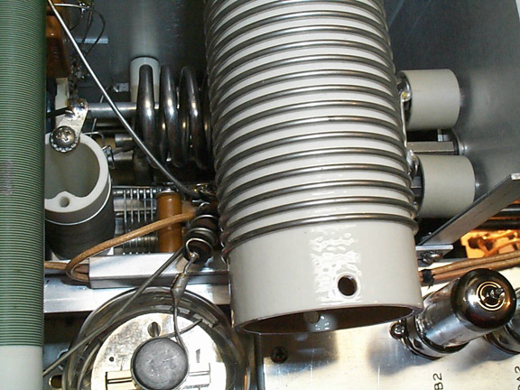


I powered it up and it all seems to work just fine! Alignment was easy except for the 80m trap adjustment on 40m - It does not null out as indicated in the manual. I decided to leave it in the position it was originally set to. Looking at the schematic I do not see how the trap works! Here's what I'm getting:
Band Grid current O/P power
80 22mA 100W
40 15mA 80W
20 15mA 85W
15 10mA 80W
10 10mA 65W
I suspect the 40m fixed loading cap is leaky (causing lower output than expected). I'm going to leave it for now.

Here's the finished transmitter prior to installation in its freshly powder coated cabinet.